The Setting area
| Trap Width | Set the width of the trapping area that will be generated. |
| Trap Color Opacity | Set the color depth of the trapping area generated by two objects. The default parameter is 100%. At this setting, the trapping area color is at its darkest, which may cause this trapping area to be more visible. Reducing the parameter value will reduce the strength of the trapping area color. |
| Allow Sliding | Select this option to implement the sliding gradient trap (a trap that occurs between two gradients). The generated trapping area will have a gradient effect and the direction of the trap will be on both sides in order to make the trap area less noticeable. If this option is not selected, the generated trapping area will have the gradient effect, but the trapping direction will be consistent and in only one direction. |
| Color Sequence | The trap direction will use the color sequence in the ink manager for direction of traps, in addition to other trapping setting. The options are:
In this example, three colors (C, M, and Y) are arranged according to two different color sequences options, with two different results after color sequence trap is executed. First color sequence |
| Over Trap | When generating trap between ‘A’ color and ‘B’ color and trap direction is from ‘A’ color to ‘B’ color, trap width is larger than the width of ‘B’ color, and ‘C’ color which is located on the other side of ‘B’ color also meets trap condition with ‘A’ color, their trap direction also is from ‘A’ color to ‘C’ color, the final trap effect is that ‘A’ color crossed ‘B’ color into ‘C’ color. |
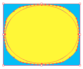
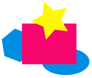
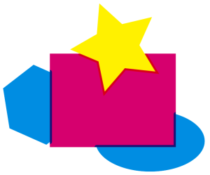
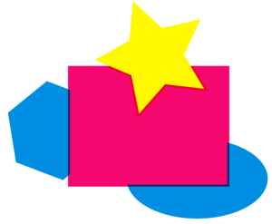
| Optimized shapes | Select this option to automatically optimize the trapping direction. Optimized shapes is not selected: Optimized shapes is selected: |
| No overflow | Due to the way that certain files are constructed, traps can overflow beyond the desired area if the No overflow setting is cleared. To prevent the trap from moving out of the desired trap areas, select the No Overflow setting. |
| Trap fill | There are four Trap fill modes:
|

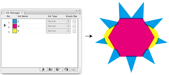
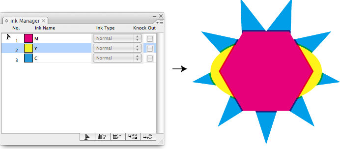


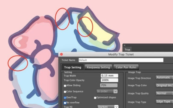
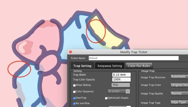

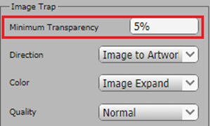
Image Trap area
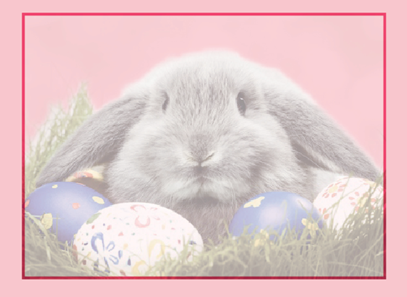
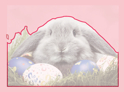
| Minimum Transparency | If the image transparency is less than the minimum value, trapping will not be generated. Trapping will be generated along the image edge when the transparency value is greater than or equal to the minimum value specified.
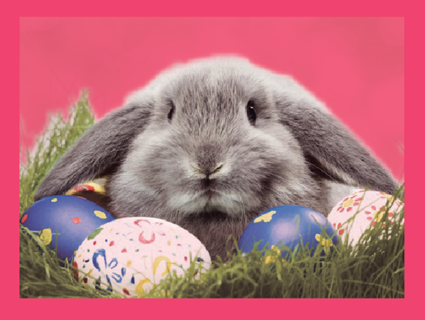
Original File:
Trap result when Minimum Transparency = 5% Trap result when Minimum Transparency = 35%
|
| Image Trap Direction | Use this parameter setting to set the image trapping direction. Options include: Automatic: Trap automatically determines and generates the direction from light to dark in accordance with the trapping rules. Trap Image to Artwork: Forces the trapping direction to expand from the images to the artwork. Trap Artwork to Image: Forces the trapping direction to expand from the artwork to the images. |
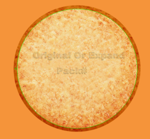
| Image Trap Color | Set the color type of image trap. Options include: Original Image Color: The result is the image data outside of the clipping mask:
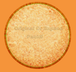
Image Expand Color: The result is the automatically generated data along the image edge. If there is a trim mask outside of the image, the data still will be generated and will not use the original data outside of the trim mask. |
| Image Trap Quality | Use this parameter to set the trap quality. Options include: Normal, Fine, and Coarse. If you choose Fine, the highest image quality of the trapping area will be generated, but the generating speed will be slow. |
| Image Trap Type | Edge Type: Extract the color from the pixels of the image edge to spread. Inside Type: Extract the color from the pixels inside of the image (excluding the edge) to spread. |
Trap Conditions
Trap condition will set text size, gap width, and ink color difference you want to trap.
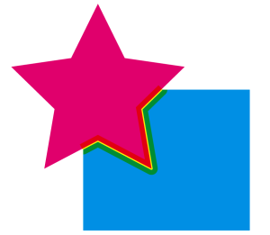
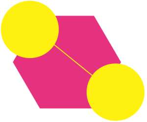
| Maximum Gap | The parameter setting range is from 0 mm to 0.5 mm. If the distance (gap) between the two objects is smaller than this set parameter value, then the gap will be filled, and determine the conditions of normal trap or pullback trap to the two padded objects; If the gap width is bigger that the defined value, then it will not fill. Example 1: Between the C and M color objects there is a Y color object with a width that is smaller than 0.1 pt created through a design error. Set "Maximum Gap = 0.1 pt", then this gap can be filled, and generate accurate trapping. Original object: A Yellow color flash (gap) is between the Magenta and Cyan color
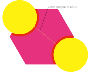
The effect after the implementation of normal trapping and without setting Maximum Gap.
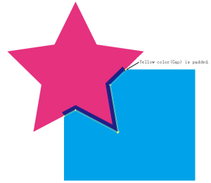
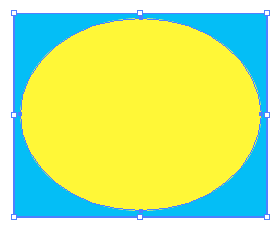
The effect after the implementation of normal trapping and padding with setting Maximum Gap = 0.1 pt. | Example 2: There is a fine line (gap) with a width smaller than 0.1pt created through a design error. By setting "Maximum Gap = 0.1 pt", area can be padded, and generate accurate trapping. Original object: A fine line (gap) is between the two Y color areas. The effect after the implementation of normal trapping and without setting Maximum Gap.
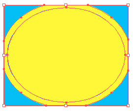
The effect after the implementation of normal trapping and padding with the setting Maximum Gap = 0.1 pt. |
| Minimum Text Size | If the font size is greater than this parameter, it will meet the conditions for trapping and will generate a new trap. | |
| Minimum Ink Difference | This parameter determines whether two adjacent objects will trap.
Description: At the left side of the > symbol the ink is a common ink within the two objects. | |


Geometry area
| Scissor | This parameter is used to set the termination position of the trapping area, to prevent the trapping area over the border of a trapped object and creating a significant change to the trap area. There are two options:
|
| End Shape | This parameter is used to set the contour shape of the trapping area entering into another object. Options include:
|
Corners | Set the corner-point shape of the trapping area. Options include:
When choosing the Miter option, it is necessary to set a parameter for the Miter Limit. |
| Miter Limit | Use this option to change the corner to a mitered (pointed) tip or to a beveled (squared-off) tip. If the length value of the trapping area mitered tip is greater than Miter Limit value × Width of trapping area, it will result in a beveled tip. If not, the result will be a mitered tip. |

Ignore area
Use these options to set the objects to not be involved in trapping.
| Patterns | If this check box is selected, Illustrator pattern objects will not be included in the trapping operation. |
| Bitmap | If this check box is selected, the bitmap objects will not be included in the trapping operation. |
| External Objects | If this check box is selected, the external objects will not be included in the trapping operation. |
| Overprint | If this check box is selected, the overprint objects will not be included in the trapping operation. |