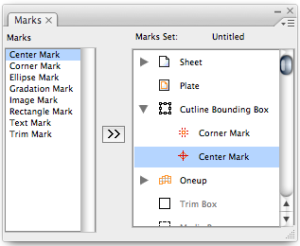
The CAD bounding box encompasses the union of cutting lines of the CAD layout file. When the document is in sheet/plate state, it is possible to add marks to the CAD bounding box.
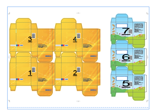
For a variety of package layouts, including those with mixed step & repeat modes, the combination of all the objects will be regarded as one imposed CAD object. All marks that have been added to the CAD bounding box will be added to the greater CAD bounding box created by the combination of all the other objects. All marks will be changed when the CAD bounding box is changed, but the relative position will remain the same.
When the document is in the sheet/plate state, the sheet and plate is deemed to have a CAD bounding box. If at this time there are no additions to the layout, marks can still be added, but these marks will not be shown in the Adobe Illustrator file. When the layout object contains the CAD cutting line, the added marks will be automatically displayed.