This process template section provides calibration and screening file information during final output.
These options are available when you select 1 in the Shades option, in the Render section of the process template.
Calibration
Curve Source
- If ColorFlow CRM is not enabled in the process template, select one of the following options:
ColorFlow Approved Snapshot—allows you to select any curve from the Print Curve or Plate Curve lists that are contained in the ColorFlow Approved Snapshot.
ColorFlow Current State—allows you to select any curve from the Print Curve or Plate Curve lists that are contained in the Current State of the ColorFlow database. When either of the ColorFlow options is selected, the HarmonyMedium option has no effect. The Minimum Dot Size option is not generally necessary for ColorFlow curves, as ColorFlow allows explicit definition of bump or cutoff curves for flexographic printing; however, this option still takes effect for ColorFlow curves if its value is greater than zero.
Harmony—allows you to select any curve from the Print Curve or Plate Curve lists that are contained in the Harmony database.
- If ColorFlow CRM is enabled in the process template, then all Calibration options are unavailable, and curves are selected according to settings in the ColorFlow CRM panel.
The disabled Curve Source control indicates the curve source selected by CRM as follows:- If the ColorFlow Approved Snapshot or ColorFlow Current State option is selected, curves are provided from the corresponding snapshot.
- If none of the options are selected, curves are provided from a numbered snapshot selected in the ColorFlow CRM panel.
- If ColorFlow CRM is not enabled in the process template, select one of the following options:
Detect pages Refined with ColorFlow
This option allows you to set a warning alert or fail output if a Job/Page has a Color Setup assigned but ColorFlow Color Relationship Management is not selected in the output process template. You can select to ignore, warn or fail. Whichever setting is selected here will also be automatically selected under Detect pages Refined with ColorFlow in the ColorConvert>Match Colors section of the output process template.
Print Curve
Select None if you do not want to apply print dot gain compensation curves to your output.
To apply a print calibration curve to your output, select the curve in the list.
If ColorFlow CRM is enabled in the process template, the disabled Print Curve control displays the name of the print curve selected by ColorFlow CRM.
If you select Harmony in the Curve Source setting, you can select Auto to automatically select the most appropriate curve. Depending on the Screening Method selected, the Harmony software determines the curve to use, based on dot shape and screen frequency data from your job or the process template. Harmony looks in the following locations in the process template:
- Dot Shape and Screen Ruling boxes
- Screen Frequency box
- Harmony Medium box
- In the Render section, the Device Resolutions box (or Resolution X and Resolution Y boxes)
If you assign a calibration curve in the Prinergy DotShop software for use on a mark, you must select the Keep DotShop Settings or Use Document's Screening, if Present screening mode.
Note: To control the application of the selected print curve for an individual page, sheet, or imposition mark, select the Calibrate check box in the Marks section of the process template. This enables you to apply print curves to imposition content without applying print curves to marks.
Plate Curve
Select None if you do not want to apply plate linearization curves to your output. This option is set to None by default.
To apply a plate curve to your output, select the curve in the list.
If ColorFlow CRM is enabled in the process template, the disabled Plate Curve control displays the name of the plate curve selected by ColorFlow CRM.
When Harmony is selected in the Curve Source setting, you must select a plate curve in the Prinergy process template, even when Print Curve is set to Auto.
Note: Plate curves are always applied to page, sheet, and imposition marks. Select None if you do not want curves applied to marks.
Harmony Medium
Available only if you select Harmony in the Curve Source setting and Auto in the Print Curve list, this option lists the Harmony media that are defined in your Harmony curve database. If the Harmony Medium list is available but the list is empty, no Harmony media are defined. The selected Harmony media is used to identify an appropriate calibration curve.
Select a Harmony media in the list.
Note: This option is not available when you select ColorFlow Approved Snapshot or ColorFlow Current State in the Curve Source setting.
Minimum Dot Size
This feature can be used to avoid scum dots on flexo plates.
For all screening beside Maxtone SX, the Minimum Dot Size specifies a Clipping value, which means that all tones below the specified minimum dot will be removed.
With Maxtone SX, the user has the option of choosing Clip or Bump. Clip will remove all tones below the specified minimum dot, whereas Bump will elevate the minimum gray value in the file to the specified minimum dot value. The default setting for Maxtone SX Minimum Dot Size is Bump.
Type the lowest tint percentage (the print condition’s minimum dot percentage), with up to one decimal place, at which you want to image dots—for example, 3% or 3.5%. This feature is only available if you have specified a Tonal Calibration curve.
The value can be up to 3.000 (default is 0.000). Up to three decimal points are accepted.
Originally implemented for use with Harmony, the Minimum Dot Size option is not generally necessary for curves created in ColorFlow, as ColorFlow allows precise definition of bump or cutoff curves for flexographic printing. The effect of this control is maintained, however, when ColorFlow curves are selected, to main correct output behavior when a Harmony curve is migrated to ColorFlow and selected for output in the process template.
Notes:
- For Maxtone FX and Maxtone SX, a 0.20 Minimum Dot Size is recommended.
- For Maxtone FX and Staccato NX, dots smaller than the specified Minimum Dot Size are printed as 0%.
- For Maxtone SX, dots smaller than the specified Minimum Dot Size are printed at the specified value.
Screening Mode
(See also the topic about document screening in this guide.)
Note: The XMP options are available only if you have a license for the XMP feature.
- Select Override all document screening to use the screening specified in the process template. This option ignores any screening specified in the source PDF file or the Prinergy DotShop software.
- Select Honor DotShop Setting from document to use the screening specified in the DotShop software, when available. For pages that are not modified in DotShop, the screening specified in the process template is used.
- Select Honor DotShop and XMP settings from document when you want DotShop and XMP settings to override the settings in the process template.
Note: DotShop settings override XMP settings since they are object-related settings while XMP are separation-related settings. - Select Honor DotShop, XMP and the following settings from the document and any DotShop, XMP or PostScript Document Screening (SetHalftoneOperator) settings override the settings in the process template. DotShop settings override XMP and PostScript Document Screening settings, since DotShop settings are object-related settings, while XMP and PostScript Document Screening are separation-related settings. If the file contains PostScript Document Screening settings, you can selectively honor angle, frequencies and/or dot shape settings by selecting any of the Angles, Frequencies, and/or Dot Shapes check boxes. However, you cannot disable any angle, frequency or dot shape settings specified by DotShop or XMP tags.
Notes:
- If Prinergy does not support the screen angles in the source PDF file, the nearest supported angle is used.
- This option offers the greatest risk of poor results, because screen angles identified in the source PDF file may not be suitable for the output device.
Screen Type and Screen System
Select a screen system for the format selected in the Output To list.
- The Maxtone family of screen types are based on the Prinergy AM (conventional or rational tangent) screening technology. For more information about the following screen types and configurable options, see the applicable topics such as Screen types and About screen systems.
- Maxtone—standard AM screen can be configured with a wide choice of rulings, angles, and dot shapes.
- Maxtone CX—highlights and shadow dot size can be configured in the Dot Width Highlights and Shadows boxes.
- Maxtone FX—highlights and shadow dot sizes can be configured in the Dot Size Highlights and Shadows lists.
Note: Maxtone FX works on the entire page, so all objects defined with Maxtone FX must have dots of the same size. If multiple dot sizes are selected, the output process will fail. - Maxtone SX—highlights and shadow dot sizes can be configured in the Dot Size Highlights and Shadows lists.
- Maxtone IS—screen set resolution must be identical to the resolution set in the Render section of the process template.
Note: Most IS screen parameters are predefined in the IS screen set and cannot be modified in the process template. For information about defining IS screen sets, see the Prinergy System Administration Guide. - Maxtone IS CX—screen set resolution must be identical to the resolution set in the Render section of the process template.
- The Kodak Staccato family of screen types are Prinergy stochastic screening technologies.
- Staccato—highlight size and angle can be configured by selecting one of eight unique screen patterns.
- Staccato NX—highlights and shadow dot size can be configured in the Dot Size Highlights and Shadows box.
About Maxtone FX or Maxtone SX Screen System (Angle sets):
Each system consists of either a 15 degree angle set or a 7.5 degree angle set—for example, the default (CMYK 82.5 22.5 7.5 52.5) is a 7.5 degree set. The following angle sets are available:
Cyan | Magenta | Yellow | Black |
|---|---|---|---|
| 15.0 | 75.0 | 0.0 | 45.0 |
| 75.0 | 15.0 | 0.0 | 45.0 |
| 15.0 | 45.0 | 0.0 | 75.0 |
| 45.0 | 15.0 | 0.0 | 75.0 |
| 75.0 | 45.0 | 0.0 | 15.0 |
| 45.0 | 75.0 | 0.0 | 15.0 |
| 15.0 | 75.0 | 30.0 | 45.0 |
| 15.0 | 75.0 | 60.0 | 45.0 |
| 22.5 | 82.5 | 07.5 | 52.5 |
| 82.5 | 22.5 | 07.5 | 52.5 |
| 22.5 | 52.5 | 07.5 | 82.5 |
| 52.5 | 22.5 | 07.5 | 82.5 |
| 82.5 | 52.5 | 07.5 | 22.5 |
| 52.5 | 82.5 | 07.5 | 22.5 |
| 22.5 | 82.5 | 37.5 | 52.5 |
| 22.5 | 82.5 | 67.5 | 52.5 |
Note: The ability to set custom screen angles using the SCDV function (see answer 30177 on Partner Place) is not available for Maxtone FX /Maxtone SX.
Dot Shape
(See also the topic about dot shapes.)
Select a dot shape in the list.
The list of available dot shapes varies, depending on the screen system selected in the Screen System list.
For Maxtone FX, select Euclidean (default), Round, or Light Eliptical.
For Maxtone SX, select Round1 or Euclidean.
Note: The Round1 dot (Maxtone SX only) behaves somewhat differently from the conventional Round dot. When the dots start to touch (at about the 78% tone value), the shape rapidly transitions to a round shape instead of retaining the diamond shape of a conventional Round dot function.
Device Resolutions
Displays the values set in the Resolution X and Resolution Y boxes in the Render section of the process template.
Screen Ruling
Select or type the desired lines per inch.
Available when Maxtone, Maxtone CX, Maxtone FX, or Maxtone SX is selected in the Screen System list.
The list of available screen rulings varies, depending on the setting in the Screen System, Device Resolutions, and Output To lists.
If you select an IS screen set, you cannot change the Screen Ruling value.
For Maxtone FX, valid values range from 80 lpi to 200 lpi.
For Maxtone SX, valid values range from 80 lpi to 300 lpi.
Preset screen rulings may include 80, 90, 95, 100, 110, 120, 133, 141, 150, 175, 190, 200, 240, and 300 lpi, or you can specify a custom value, such as 160 lpi.
Feature Size (Highlights, Shadows)
Available when Staccato or Staccato NX is selected in the Screen System list.
Select the most appropriate feature size (in microns or pixels) for the print condition. A smaller number produces finer-grained output.
The list of available feature sizes varies, depending on the setting in the Screen System, Screen Ruling (Staccato NX), Device Resolutions, and Output To lists.
Note: The Staccato feature sizes normally denote a dot size somewhere between the actual highlight and the midtone dot size. However, Staccato feature sizes listed as <##>.1 indicate a first-order screen, where <##> is the exact dot size of the highlight and quarter tone dots.
Note: The Staccato NX feature size denotes the exact dot size of the highlight dots in pixels.
Note: It is also possible to select the dot size for the highlights and shadows using DotShop Composer. Maxtone FX works on the entire page, so all objects defined with Maxtone FX must have dots of the same size. If there are multiple dot sizes selected, the output process will fail.
Midtone Frequency
Available when Staccato NX is selected in the Screen Type and Screen System lists.
Select a Staccato NX midtone frequency in the list. A larger number indicates a finer dot structure.
Midtones are specified as a frequency, even though the dot structures are randomized. Frequency is expressed in lines per inch (lpi) and is a useful metric with AM and FM screens when assessing qualitative, lithographic, and imaging behavior. The specified Staccato NX midtone frequencies indicate the midtone dot gain and press performance that you would expect from equivalent Maxtone and Maxtone FX screen rulings.
Screen Color
In the Screen Color and at Angle boxes, perform the following tasks:
- Set screening for colors other than the four process colors
- Swap the process color screens within screen systems
- Assign a screen to the "Default" color. This screen will be used for any color that doesn't have its own screening value in the output process template or color database.
The screen angles associated with each process color in the at Angle box vary, depending on the setting in the Screen System and Dot Shape lists.
To assign a screen to a color in the Screen Color box, type the name of a spot color, or type Default to select the default screen angle. Use the correct capitalization and spacing in color names.
Note: To swap two screens (for example, magenta for black), modify the entries for both colors. In this example, modify the setting in the at Angle box for magenta to use the black screen, and modify the setting in the at Anglebox for black to use the magenta screen.
Default Spot Color Handling
Determines how Prinergy assigns screen angles to spot colors that do not have screen angles assigned in the Screen Color and at Angle boxes or in the Color Editor.
To choose C, M, Y, or K as the default color screen angle, select Screen as. To cycle through the available color screen angles, select Cycle Through Screen Angles.
Screen as
To assign a different default spot color screen angle, select a color in the list.
For IS screening, Prinergy cannot assign the Others angle as the default spot color angle.
Cycle Through Screen Angles
Select this option to assign default spot color screen angles cyclically to the available process colors, in CMYK order. Prinergy does not assign process colors that have already been used to screen a spot color.
If Staccato Extended is selected in the Screen System list, the list of screens cycles from Screen #1 through to Screen #10.
For IS screening, Prinergy cannot cycle through angles other than CMYK.
Do not increase yellow ruling
To reduce moiré, the AM screening algorithm provides yellow screen frequencies (lpi) that are up to 14% higher than the cyan, magenta, and black screens. If you want a Y screen that is more similar to the Y screen in Prinergy 2.2 and earlier, select this check box. It limits yellow screen frequencies to between -4% and 4% of the ruling of the C, M, and K screens. For example, if the C, M, and K screens are at 150 lpi, this check box limits the screening algorithm to providing a Y screen between 144 lpi and 156 lpi.
This setting does not affect the yellow frequency of an IS screen set. To change the yellow frequency of an IS screen set, use the IS Screen Set Editor.
Maxtone SX Highlight Smoothing
For the smoothest tonal transitions to and within highlight areas, select this check box to apply the smoothing algorithm that is available only via Maxtone SX screening.
This algorithm provides a smoother transition from FM to AM by compensating for different physical and optical dot gain occurring at the point where dots transition from primarily being added to primarily being grown. (The actual inflection point varies, depending on pixel size and frequency.)
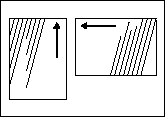
Rotate Screens With Pages
Select to rotate screens with reader orientation for each page in an imposition.
When some pages are rotated 90°, rotating screens with the pages allows all pages to be screened at the same angle.
Screens are only rotated at 90° so pages that are oriented at other angles are not affected. The result of rotating screens is apparent when you screen with dot shapes that are not rotationally symmetric, such as Elliptical and Line.
|
|
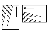
Mirror Screens with Output
Select to mirror screens so they are consistent across all devices (for output devices that have intrinsically mirrored output).
Note: This will affect the screen angle rotation on the printed page and should be used only for compatibility with legacy printing.
When the Mirror Screens with Output check box is selected, selecting the Mirror Print check box in the Device section of the process template causes screen angles to become mirrored with the output. This is useful for some printing processes that require mirrored film or plates, to ensure consistency of screen angles with digital dot proofs.
|
|
Note: If Round is selected in the Dot Shape list, the Rotate Screens With Pages and Mirror Screens With Output selections don't affect output.
Set Halftone Phase for each Page
Select to have the renderer reset the origin of the halftone screen for each page on an imposition.
When selected, this option ensures that each page on an imposition has the same bitmap pattern.
This is useful for a label printer who wants each label on the imposition to be identical. A difference in the halftone screen origin for each label can sometimes show up as a visible difference at the edges of the labels.
Screen Solids
Applies a screening pattern to solid areas in order to better absorb excess ink. This screening feature results in cleaner printing of solid areas.
Screen solids can also be effective in reducing ink consumption during proofing.
In the as box, type a value between 0% and 99.8% to indicate the percentage at which you want to screen all objects with solid (100%) tint.
Maxtone CX
Dot Width
Note: This option is not available when Maxtone or Staccato is selected in the Screen Types list.
Highlights
Type the size (in microns) of the Maxtone dot for highlights.
Shadows
Type the size (in microns) of the Maxtone reverse dot for shadows.
Maxtone FX / Maxtone SX
Dot Size
In the Dot Size box, select the dot dimensions (in pixels) from the Highlights and Shadows lists.
Available feature sizes depend on whether you have selected Maxtone FX or Maxtone SX in the Screen Types list.
- For Maxtone FX, feature sizes are 1x1, 1x2, 2x2, 2x3, 3x3, 3x4, 4x4, with 2x2 as the default for Highlights, and None as the default for Shadows.
- For Maxtone SX, feature sizes depend on the output resolution selected:
- For Maxtone FX, feature sizes are 1x1, 1x2, 2x2, 2x3, 3x3, 3x4, 4x4, with 2x2 as the default for Highlights, and None as the default for Shadows.
- For resolutions < 3600 dpi, feature sizes are None, 1x2, 2x2, 2x3, 3x3, 3x4, 4x4, 5x5, 6x6, with 2x2 as the default for Highlights and None as the default for Shadows.
- For resolutions > 3600 dpi, feature sizes are None, 4x4, 5x5, 6x6, 7x7, 8x8, 9x9, 10x10, 11x11, 12x12, with 4x4 as the default for Highlights and None as the default for Shadows.
HyperFlex
Screening technology that allows for smaller dots and/or graphic elements to be held on flexo plates during UV exposure of a plate.
For more information about HyperFlex, see the Prinergy Advanced Flexo User Guide.
HyperFlex Classic
When imaging on flexo plates, select to enhance Maxtone dots with Kodak HyperFlex Classic technology.
Note: Hyperflex Classic is not intended for offset use.
In the extreme highlight areas, Maxtone simulates FM screening by randomly removing dots from the AM grid. HyperFlex Classic helps to support and strengthen Maxtone by placing light valves where dots have been removed.
Pixels
Type the HyperFlex dot size in pixels.
To determine the proper HyperFlex dot size, you must perform a series of flexo exposure tests. For more information, see the Prinergy Advanced Flexo Implementation User Guide.
HyperFlex Advanced
In flexo applications, select to use HyperFlex Advanced with Maxtone, Maxtone CX, Maxtone FX, Maxtone IS, Maxtone IS CX, and Staccato NX screen types.
Note: Hyperflex Advanced is not intended for offset use.
HyperFlex Advanced places light valves around halftone dots to strengthen and support individual dots.
Size
Type the size of the light valve in pixels. The minimum value is 1 and the maximum value is 16.
As feathering (a reduction in HyperFlex size as tone value increases) is being applied, this value specifies the starting size of the light valve. The light valve size is scaled back, in a linear fashion, to zero (at the tint percentage specified in the Limit box).
Distance: Start/End
Type the distance between the center of the light valve and the center of the dot.
Suggested settings—Type the same values in the Start and End boxes, and use a larger value than you enter in the Merge Distance box. For example, type 2 in both the Start and End boxes, and type 1 in the Merge Distance box. This positions the light valves equidistant between adjacent halftone dots.
If you are not using the suggested settings, in the Start box, type the distance from the light valve to the center of the smallest halftone dot. In the End box, type the distance (in pixels) from the light valve to the center of the largest dot, as specified in the Limit box.
Merge Distance
Type a value that determines where the light valves will be positioned in relation to the halftone dots.
Suggested settings—Type the same values in the Start and End boxes. Type a smaller value in the Merge Distance box than you entered in the Start and End boxes. For example, type 2 in both the Start and Endboxes, and type 1 in the Merge Distance box. This positions the light valves equidistant between adjacent halftone dots.
Limit
Type the tint percentage above which HyperFlex Advanced will no longer be applied. The general recommendation is to set the Limit between 20% and 50%.
DigiCap
Kodak DigiCap is screening software for digital photopolymer (flexo) media that improves the transfer of ink in solid areas, using small reverse dots (a tint).
Set the DigiCap texture by specifying the size of the reverse dots and the tint percentage. In the Texture with boxes, type the length and width of the reverse dots. The maximum size is 10 pixels by 10 pixels.
In the as box, type the tint percentage. For example, a 92% tint creates an area with 8% coverage of reverse dots.
To determine the proper DigiCap feature size and percentage, you must perform a print test containing multiple combinations of coarseness levels and tint percentages. You cannot determine the feature size or percentage without comprehensive press tests. For more information, see the Prinergy Advanced Flexo Implementation User Guide.
In the Keepaway box, type the distance (in pixels) between the edge of elements to which DigiCap texturizing should not be applied and the start of DigiCap texturizing.
Custom Pattern
Select this check box to use the DigiCap pattern settings from a Custom Pattern file instead of setting the size of the reverse dots and the tint percentage in the process template. After you select the Custom Pattern check box, type the name of the Custom Pattern file in the Custom Pattern box (filename.raw or foldername\filename.raw) or click the arrow, browse to the file and select it.
Requirements for using this option:
- The Custom Pattern file must reside on the Prinergy server in the
\\<ServerName>\AraxiHome\CreoAraxi\data\Screening\DigiCapfolder. You may create subfolders in this location but if you place the Custom Pattern file in such a subfolder, you must specify the name of the folder in the Custom Pattern box, for example:foldername\filename.raw. - Before you can use this option, you must first create an Output JTP of a Proofing Device Extended type in Prinergy Administrator and then select this JTP in the Render section of the output process template.
- The Custom Pattern file must have the following properties to be processed by the Printer JTP:
- 8-bit Grayscale image file
- Black or white pixels only
- Identical image width and height
- Saved in Photoshop RAW format (Note 1)
- The Custom Pattern file must reside on the Prinergy server in the
How the Printer JTP applies a Custom Pattern
Each pixel in the Custom Pattern file affects one pixel in the output raster, regardless of the file and output resolutions. The JTP steps and repeats the Custom Pattern image, horizontally and vertically, to cover the entire output image area. If a pixel in the stepped pattern image is white, then it makes the corresponding output pixel white, unless Keepaway applies, as follows: if Keepaway = 1, then black pixels within 1 pixel of a white region will not be changed to white.
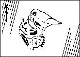
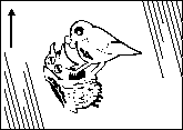
The following illustrations show the effect of the provided Sample64x64.raw Custom Pattern file, selected in the Custom Pattern box, with Keepaway = 1.
The left graphic is a 6-point Times ”r“ character, rendered at 2400 dpi. The center graphic is the Sample64x64.raw pattern, tiled to the same size as the other graphics. The right graphic shows output with DigiCap applied.

Creating a Custom Pattern
- The custom pattern can be any pattern that looks smooth and uniform when viewed from a distance equivalent to viewing a plate or printed sheet with the naked eye.
- The custom pattern is stepped by the Printer JTP, so the pattern edges must align without creating a visible artifact. To check this in Photoshop, apply Filter > Other > Offset… Enter Horizontal and Vertical shift values that are about half the pattern size, and select Undefined Areas: Wrap Around.
- The size and density of pixel clusters in the pattern should be adjusted, through experimentation, to provide consistent ink density across the solid areas of the printed sample.