Overview
This document assumes that impositions are created with Preps or with the create impositionprocess template in Prinergy Evo. If you are imposing manually in a page layout software (such asQuarkXPress® or Adobe InDesign), se <link>.
Preps Imposition Information
In Preps impositions, the press sheet represents the media (such as paper or another substrate) that the job is printed on, and you lay out the imposition within the press sheet. The press sheet is then positioned within a selected Preps device, which represents the plate that is used on press.
Depending on the type of layout you select, Prinergy Evo either uses the imposition sheet or the Preps device to position output or define the output size.
Preps Devices
Preps devices are media-size definitions based on PostScript PrinterDescriptions (PPDs) from device software, such as Print Consolesoftware and Xpo. A PPD contains output-device specific information, including fonts, margins, supported page sizes, and so on. In general,Preps devices must be configured to be the same size or larger than theimposition sheet of a given layout.
Note: Do not use the Prinergy Refiner PPD for Preps devices. Prepsdevices should be created from PPDs generated by software like PrintConsole and Xpo.
Digital media size with Preps impositions
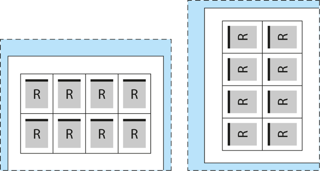
If you select Digital media size in the output from imposition process template, then the Preps device size determines the basic size of the output. Output is the same size as the Preps device used.
In the diagram below, the white box with the solid edge represents the Preps impositions sheet, while the light blue area with the dashed border represents the Preps device (aka. plate).
Cut sheet media size with Preps impositions
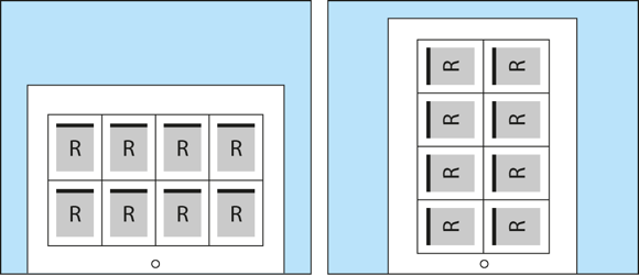
If you select Cut sheet, then the size of the Preps device is mostly ignored by Prinergy Evo during output. Instead, Prinergy Evo positions the imposition sheet to the media size defined in the process template.
In the diagram below, the white box with the solid edge represents the Preps impositions sheet, while the light blue area with the solid border represents the media defined by Prinergy Evo's cut sheet setting.
Press Sheet Size device
If you are using a Preps device with Cut sheet, sometimes output may appear shifted on plate due to unexpected offsets within the Preps device. To get around this problem, the Press Sheet Size device was created in Preps and in the create imposition feature in Prinergy Evo.
The Press Sheet Size is a variable size Preps device that snaps to the imposition sheet edge. This means that this device can be used for any imposition sheet size and no unexpected offsets appear in the final output.
Layout Positioning Using Output From Imposition
This section addresses positioning imposition layouts with Cut sheet media. Only Cut sheet allows you to specify where output is positioned, because Digital always adjusts to fit the layout—there is no such thing as aligning or shifting within Digital media. As you move a layout on Digital media, the media moves with it.
Alignment Settings
When you select Cut sheet, alignment settings can be used to position the layout to the media. In the Layout Placement section, you can select nine different positions for the layout, as shown in the following diagram.
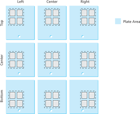
Note: When aligning a layout it is important to remember that elements move, while the media remains stationary.
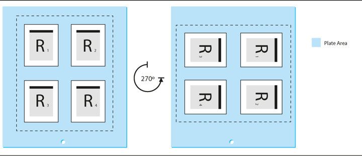
Whether a layout is heads-up or heads-right, aligning to the bottom-center of the media will put the content in the same location of the plate: layout is rotating within the alignment position.
Shift Settings
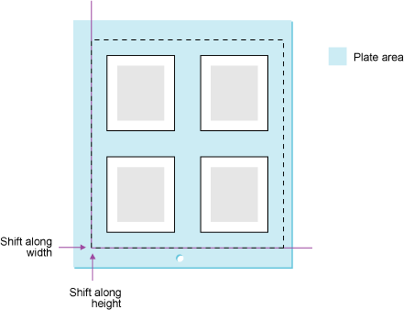
Select the Shift Along Width box to shift the layout, signature, or page from the left edge of the media along the horizontal axis. Select the Shift Along Height box to shift the layout, signature, or page from the bottom edge of the media along the vertical axis. Adding positive values in the boxes moves the layout away from the origin edge. Adding negative values in the boxes moves the layout closer to the origin edge.
Orientation Settings
Orientation settings are used to rotate the layout. With regard to how you use the layout controls, orientation can be thought of as being applied last to the layout. In the case of Cut sheet media, orientation is used to rotate content within a fixed media size. This comes back to the pasteboard analogy. The orientation settings rotate the layout (the placed content) against the fixed Cut sheet media (the stationary pasteboard).
Heads Direction Controls
The heads direction controls are used to rotate the entire layout in increments of 90 degrees. The heads direction radio buttons for output from PDF show four options: heads-up  , heads-down
 ![]() , heads-right
, heads-right ![]() , and heads-left
, and heads-left  . This defines the heads direction of the content within output. In output from PDF this defines the direction for every page, since pages cannot be rotated independently of the layout that contains them.
Flat Rotation
Flat rotation is a setting that allows you to apply a small angle rotation to the layout to compensate for printing artifacts caused by content, or to compensate in the image for plate cocking. Plate cocking is a small rotation of the image on a plate, intended to compensate for misregistration caused by worn or misaligned press components.
Sheet, Page, and Slugline Marks
- When using marks with an output from imposition process template, you can position page marks at the left, right, bottom, or top of a page. By default, page marks are positioned at the top of a page.
- You can position the sheet marks on the left, right, bottom, or top of a sheet
- When a layout is rotated, page and sheet marks are also rotated. Slugline marks, however, are attached to the media and do not rotate.
- When adding page and sheet marks to imposition proofs, make sure the marks are the correct size to fit in the margins and gutters defined in the imposition or layout. Marks that are too large will appear over content.
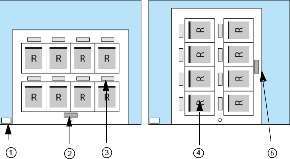
- Slugline mark
- Sheet mark
- Page mark
- Page
- Edge of sheet
Page and Sheet Mark Positioning
The at Distance boxes in the Layout section control the positioning of page and sheet marks. In the following example, both the page and sheet mark are positioned at the top. Page marks are positioned on the outside edge of a page; sheet marks are positioned on the inside edge of the sheet edge.
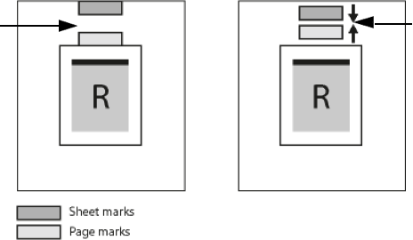
- Left: If you type 0 in the at Distance boxes, Prinergy Evo positions the page and sheet marks so they are adjacent to the page and the edge of the sheet.
- Right: By adding 0.5 in the at Distance boxes, Prinergy Evo moves the page mark away from the page and the sheet mark away from the edge of the sheet (pushing the marks closer together).
In the following example, the page mark is positioned at the top and thesheet mark is positioned at the bottom.
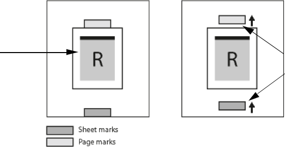
- Left: If you type 0 in the at Distance boxes, Prinergy Evo positions the page and sheet marks so they are adjacent to the page and the edge of the sheet.
- Right: By adding 0.5 in the at Distance boxes, Prinergy Evo moves the page mark away from the page and the sheet mark away from the edge of the sheet.