You can adjust the profile at a selected color. A scenario where you would use this would be when certain input color builds have a degree of lightness or color inaccuracy that requires adjustments to another CIELAB value. For example, a brand color that is not mapped correctly and has little impact on the surrounding colors.
You can fine-tune and adjust the selected color by restricting the ranges of Lightness, Chroma, and Hue with the Adjustment Range sliders.
- When you adjusting the simulation or conversion DeviceLink, in the DeviceLink tab, click Selected Color.
- Do the following:
- To enter the color input coordinates that you want to adjust, in the DeviceLink Tints section, enter the C, M, Y, and K values in the In column.
- To select a color from an image:
- Click Preview or Select Color.
- Select the image file and click Open.
- In the Image Preview dialog box, click the + icon to enable the Colorimeter.
- Place the Colorimeter at the place you want to adjust.
- In the DeviceLink tab, click Select Color.
The entered or selected color appears in the color patch.
The Selected Color L* text box shows the selected color lightness value.
The Selected Color C* text box shows the selected color chroma value.
The Selected Color h* text box shows the selected color hue angle.
- You can adjust the lightness range, chroma range, hue range, and color extent:
- To adjust the color extent, enter a value or move the slider in the Color Extent control
- To adjust the lightness range, move the range sliders in the Lightness Range control
- To adjust the chroma range, select the Advanced Ranges check box, and then move the range sliders in the Chroma Range control
- To adjust the hue range, select the Advanced Ranges check box, and then move the range sliders in the Hue control
- To adjust the color extent, enter a value or move the slider in the Color Extent control
- You can apply your adjustments to other tint values that have the same color as the selected color. For example, CMYK inputs (0, 30, 50, 20) and (12, 40, 60, 0) have the same darkened orange color. If you are adjusting selected color (0, 30, 50, 20), to apply your adjustments to input (12, 40, 60, 0) and all the other CMYK inputs that have this same darkened orange color, select the Adjust all inputs with selected color appearance check box.
-
The color patch displays the output color. If the displayed color does not visually align to the color on your proof or press sheet, you can adjust the displayed color in the color patch:
- To reset the display to the default displayed color, click the Reset icon
 .
.
- To reset the display to the default displayed color, click the Reset icon
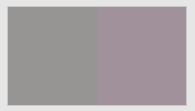
- The displayed color patch demonstrates the effect of your adjustments.
The color produced before your adjustment is shown on the left. Your adjustment is shown on the right.
- To display the color patch in a larger view for easier color comparison, click anywhere in the color patch.
- Adjust color cast, lightness, or both by the following:
- Use the lightness (L*) slider
 to make the color darker or lighter. You can also enter the L* value directly in the Color Change columns.
 - Use the cast (a*b*) selector
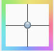 to adjust the color cast. You can also enter the a*, b* values directly in the Color Change columns.
-
You can:
- View the effect of your adjustments on an image before you apply your changes
- Undo or redo your previous adjustments
- To save your changes, click Apply.