The ColorFlow section in a Prinergy output process template, identifies how ColorFlow settings will be applied during output.
Prinergy output process templates include:
- Loose Page Output
- Imposition Output
- Final Output
When you configure the ColorFlow settings in an output process template, you select the device, device condition, and plate line, but not a color setup. The color setup used is the one that was assigned to the page files when they were refined—that is, either the color setup specified in the refine process template that was used or the job's default color setup. The color setup that is used during output processing is the color setup specified for each artwork file in the Color Setup column in the Pages pane.
warning: Output will fail if the color setup does not match the color setup assigned during refine, unless the Allow color setup mismatch option is enabled.
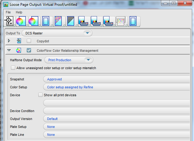
When you configure the ColorFlow settings in an output process template, you can make the following selections:
- Halftone Output Mode:
- Print Production—This halftone output mode reflects the standard operation of Prinergy and ColorFlow for production.
- Print Characterization—This halftone output mode is used to print and measure the response of a print device.
- Plate Verification—This halftone output mode is used to verify the linear response of plates produced by a particular plate line (consisting of the computer-to-plate device, plate processor setup, and chemistry), with a selected screening system.
- Plate Characterization—This halftone output mode supports imaging and measuring the uncalibrated (or intrinsic) response of a plating line, such that a plate linearization curve can be computed.
- Snapshot—A ColorFlow snapshot captures the state of the entire color database, making its elements available to the workflow and providing a convenient backup. The snapshots feature makes it unnecessary for you to manually save and name multiple versions of your color control elements after adjusting them. At any time, you can revert to the state of a previous snapshot in the ColorFlow software. When you have competed your work in ColorFlow to a certain level and you are satisfied with the elements in color setups, you will mark a snapshot as Approved.
- Color Setup—This list displays the names of all color setups in the selected snapshot. At the top of the list is Color setups assigned by Refine, followed by Job color setup.
- Device—An individual occurrence of a physical device that captures or produces an image. Devices have a type and customer-specified properties, such as a name and location in the plant. Because the declaration of a device does not include its operating conditions—such as ink selection, type of screening, and paper—you cannot measure the color response of a device on its own.
- Device Condition—A combination of a device and the operating conditions in which the device captures or produces an image. A device condition has a known color response. Device conditions can be divided into groups such as print conditions (press and proofer devices), capture conditions (scanner and camera devices), and reference print conditions (industry specifications). A device condition can include more than one device if all the devices are the same device type, they use the same consumables and operational settings, and they can be calibrated to yield the same color response.
- Plate Setup— If the selected device condition uses a plate setup in the selected snapshot, this plate setup is displayed here. Otherwise, this list displays None. This list is not available when a process template is configured for continuous-tone (non-screened) output.
- Plate Line—To determine the behavior of a particular plating line, plate type, and screening combination, you must image a plate control strip (such as the Kodak Image Control Strip test image) on a plate, manually measure the resulting dot area values on the plate, and type your required values in the Plate Setups dialog box in ColorFlow. A ColorFlow plate line is associated with only one plate setup. In your shop, you may use a platesetter and chemistry to process several different screenings. To model this, in ColorFlow, create similar plate lines in the other plate setups. You can name them to match the equipment in your plant. You may want to create several plate lines to indicate when chemistry changes occur. For example, if you routinely change solutions on Mondays, you might create different ColorFlow plate lines for Monday, Wednesday, and Friday. This list is not available when a process template is configured for continuous-tone (non-screened) output.
- Task preparations
- Create a loose page output
- Create an imposed output
- Create final output
- Delete the process template and process template group
Task preparations
To prepare for the following task, you will need to re-refine the PDF pages again using the sample color setup.
Note: Only complete these steps if you changed the original color setup (sample color setup) to US Web Coated SWOP (or another color setup) in Task 4.
- In Job Manager, select the Pages view.
- In the Pages pane, select all PDF pages.
- Right-click a selected PDF page and choose: Refine > XXRefineGroup > XXCFRefineTemplate.
- In the Start Process dialog box, click OK. As the sample color setup is the job's default color setup, the PDF pages will be re-refined using this color setup.
Note: The following procedures describe how to edit an existing process template prior to output. The recommended practice for achieving a standardized ColorFlow output process would be to create a specific ColorFlow process template using the Process Template Editor.
Note: For the purposes of this training, the following procedures outline how to edit an existing template using the Start Process dialog box. A process template Start Process dialog box gives you the option to edit the process template before running it. When you edit a process template in this way, any changes to the process template are temporary and are discarded once the process is complete.
Create a loose page output
The following describes how to create loose page output that includes ColorFlow color control elements. In this example, you will edit an existing Prinergy VPS software loose page output process template to enable ColorFlow.
The recommended practice is to create an established ColorFlow output process template, however, for the purposes of this task, an established process template will be temporarily edited. The edit will be lost after the process is complete.
- In Job Manager, select all PDF pages in the Pages pane.
- Right-click a selected PDF page and choose: Loose Page Output > Virtual Proof > Virtual Proof.LoosePage.
- In the Start Process dialog box, click the Edit Process Template button.
- Enable the ColorFlow Color Relationship Management section. View all available options.
- In the Halftone Output Mode list, select Print Production.
- In the Device list, select sample proofer.
- In the Device Condition list verify that the sample condition is selected: sample resolution, sample substrate, Inkjet Proofer - Matchprint Inkjet, CMYK
This sample condition is shipped with the Prinergy system. - Open the ColorConvert section.
- Enable the Match Colors in Page Content option.
- Click OK.
- In the Start Process dialog box, click OK.
- Select all PDF pages in the Pages pane. Right-click any selected page and choose Open VPS files. The VPS software automatically opens and displays the PDF pages containing the ColorFlow color setup data.
Create an imposed output
The following describes how to create imposed output that includes ColorFlow color control elements. In this example, you will edit an existing Prinergy VPS software imposition output process template to enable ColorFlow.
The recommended practice is to create an established ColorFlow output process template, however, for the purposes of this task, an established process template will be temporarily edited. The edit will be lost after the process is complete.
- In Job Manager, select the Signatures view.
- In the Imposition Plans pane, right-click Wells (1 Signature, 8 pages) and choose: Imposition Output > Virtual Proof > Virtual Proof.Imposed.600.
- In the Start Process dialog box, click the Edit Process Template button.
- Enable the ColorFlow Color Relationship Management section. View all available options.
- In the Halftone Output Mode list, select Print Production.
- In the Device list, select sample proofer.
- In the Device Condition list verify that the sample condition is selected: sample resolution, sample substrate, Inkjet Proofer - Matchprint Inkjet, CMYK
This sample condition is shipped with the Prinergy system. - Open the ColorConvert section.
- Enable the Match Colors in Page Content option.
- Click OK.
- In the Start Process dialog box, click OK.
- In the Imposition Plans pane, right-click Wells (1 Signature, 8 pages) and choose Open VPS files. Prinergy VPS software will automatically open and display the imposition containing the ColorFlow color setup data.
Create final output
The following describes how to create final output that includes ColorFlow color control elements. In this example, you will edit an existing final output process template to enable ColorFlow.
The recommended practice is to create an established ColorFlow output process template; however, for the purposes of this task, an established process template will be temporarily edited. The edit will be lost after the process is complete.
Note: As this activity can't realistically emulate final output to a platesetter device, the following procedures outline how to generate TIFF files for each color separation, and save them to a storage folder in your Prinergy job folder.
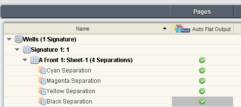
- In Job Manager, select the Separations view.
- Right-click Wells (1 Signature) and choose: Final Output > Auto Flat Output > AutoFlatOutput.
- In the Start Process dialog box, click the Edit Process Template button.
- In the Output To list, select TIFF.
- Enable the ColorFlow Color Relationship Management section. View all available options.
- In the Halftone Output Mode list, select Print Production.
- In the Device list, select sample press.
- In the Device Condition list verify that the sample condition is selected: sample screening, sample substrate, Offset Press - Sheetfed, CMYK
This sample condition is shipped with the Prinergy system. - Verify that the ColorConvert section is not selected.
- Open the Device section. In the Output Type section, select Absolute File or Printer.
- Click the Browse button beside the Device Path window. Navigate to your Prinergy job folder that contains the
Final Outputfolder created in Task 2:Volumes / AraxiVolume_<ServerName>_J / Jobs / XXJob24 / UserDefinedFolders / Final Output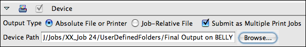
- Click OK.
- In the Start Process dialog box, click OK.
- At the completion of the final output process, verify that all separations were successfully processed in Job Manager.
- Right-click the XXJob24 folder icon in the bottom left corner of Job Manager. Select Open Job Folder in File Browser.
- Open
UserDefinedFolders / Final Outputto view the TIFF files generated during the final output process.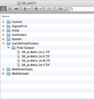
Delete the process template and process template group
- From the Tools menu, choose Process Template Editor.
- In the Refine group, open your refine group XXRefineGroup.
- Right-click your process template XXCFRefine Template and select Delete. The process template is deleted.
- Right-click your refine group XXRefineGroup and select Delete. The process template group is deleted.
- Close the Process Template Editor.
- Close XXJob24 Job Manager.