This process template section defines how Prinergy places the pages on the output media during imposition output.
Media
Media Configuration
This option becomes available when you select Kodak Proofers in the Output To list.
Specifies the type of paper you're using in the Kodak proofing device. Select a paper type from the list.
Thickness
This option becomes available when you select an Epson device in the Output To list.
Type the thickness of the paper you are using in the Thickness box, and then select a unit of measurement.
Layout for Kodak Proofers
Select a template to control how multiple pages are arranged on a single proof.
This box is available only for those proofers that are connected via Kodak Proofing Software (KPS).
For more information, see the Kodak proofer documentation.
Name
Available when a vendor's device has been defined through Prinergy Administrator. Available options are determined by the device.
Size
Determines the size of the media to which you will output the final files.
Select Digital to generate an output file, for example, a file for Virtual Proofing System software. When you select Digital, the Min Width, Min Height, Max Width, Max Height, and Layout is 90° Different Than Media boxes are unavailable.
Select Cut sheet, Roll fed, or Roll fed (transverse), depending on the media being used.
Prinergy Workflow's ability to generate to physical media of particular sizes is governed by Device Connectivity Licenses, which are included in Output Packs and some base configurations. Output sizes are defined as 2-up, 4-up, 8-up, and VLF.
- 2-up license allows for physical output up to 22"
- 4-up license allows for physical output up to 39"
- 8-up license allows for physical output up to 48"
- VLF license allows for physical output larger than 48"
Min Width
Sets the minimum width for the specified media in the unit of measure selected in the list.
Min Height
Sets the minimum height for the specified media in the unit of measure selected in the list.
For cut sheet, type the sheet height. For roll fed, type the height of the smallest proof you want to make on the device.
Max Width
Sets the maximum width for the specified media in the unit of measure selected in the list.
Max Height
Sets the maximum height for the specified media in the unit of measure selected in the list.
Duplexing
This option is available for composite files; it is unavailable for separated files.
Specifies the type of duplexing.
From the Duplexing box, select Turn or Tumble to enable this feature. Select None to disable duplexing.
Front Shift and Back Shift
The Front Shift Along Width...Along Height and Back Shift Along Width...Along Height options give finer adjustment when aligning two-sided proofs than with Center Along Width/Height. Use these measurements to shift and align front and back pages along their turn or tumble axes, depending on the page or imposition/layout orientation (portrait or landscape).
These options are available only when Duplexing has been set to Turn or Tumble.
You can specify the shift in points, inches, centimeters, or millimeters.
Placement
Orientation
(See Example: orientation)
Rotates an entire imposition as a unit.
Select Auto clockwise to automatically rotate an image clockwise when rotating would result in a better fit.
Select Auto counterclockwise to automatically rotate an image counterclockwise when rotating would result in a better fit.
Center Along Width
Centers the imposition plan along the horizontal axis of the media.
Center Along Height
Centers the imposition plan along the vertical axis of the media.
Shift Along Width
(See Example: shifting images horizontally and vertically)
Available if the Center Along Width check box is cleared.
Shifts the imposition plan from the left edge of the media along the horizontal axis.
Shift Along Height
(See Example: shifting images horizontally and vertically)
Available if the Center Along Height check box is cleared.
Shifts the imposition plan from the bottom edge of the media along the vertical axis.
Flat Rotation
Makes a small angle rotation of the flat or output image. Also called plate cocking. Derive the (0.0) percentage value, or gradient, in one of two ways:
- Physically measure the first occurrence of a rotation to find the gradient that you can then apply for all jobs that use that rotation.
- Convert a given angle into its gradient.
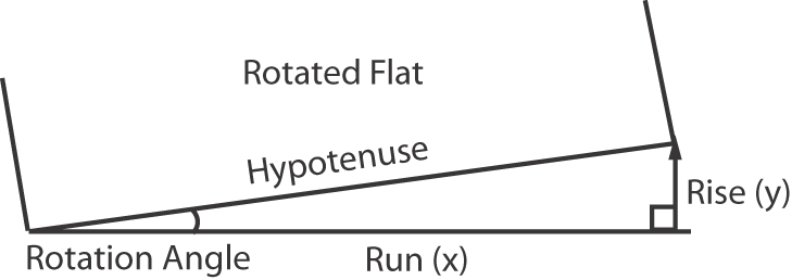
To measure for a gradient, use this formula: gradient = rise/run x 100, where:
- Rise (y-axis): measure the distance between where the flat's rotating corner started and where it must be moved as a straight line that meets the x-axis at a 90° angle. Example: 2 units
- Run (x-axis): measure the distance along the x-axis from the non-rotated corner of the flat to the point where the vertical line transects the x-axis at a right angle. Example: 90 units
- Calculation: 2/90 x 100 = 2.2
- The maximum percentage value is 3.1.
To convert an angle to a gradient, use this formula: gradient = tangent of the angle of rotation x 100, where:
- Calculation using a scientific calculator and an angle of 0.5°:
- 0.5° + Tan(gent) key = 0.008 x 100 = 0.8
- The maximum angle of rotation is 1.78°.
Note: To convert a gradient to an angle, enter the gradient into the calculator and apply the inverse tangent function. Example: 2.2% is entered as 0.022 + Inv(erse) key + Tan key = 1.26°. - Indicate whether the rotation is to be clockwise or counterclockwise.
Note: The process template does not let you select flat rotation and web growth at the same time. However, when web growth is applied, flat rotation can be specified in the web growth profile.
Punch Setting
Available when a format for an imagesetter that has an automatic punching system (for example, Kodak Magnus VLF platesetter) is selected in the Output To list.
Select a punch type. For more information about punch types, see your device documentation.
Scaling
Scale Vector
Applies scaling to the layout prior to screening the file. The scaling is based on vector data (PDF data).
Apply Scaling from Layout
Select to use the scaling specified in the original layout application, for example, Pandora.
Note: This option is not compatible with Preps.
Custom
Type scaling percentages for the Along Width and Along Height directions.
Fit to Media Size
If the specified layout produces an image too large for the media, the image is scaled to fit.
You cannot see the scaling percentage. Select this check box only when a proof scaled to an unspecified reduction is acceptable.
Non-Printable Margin
If the Fit to Media Size option was selected, you can identify the non-printable margins that should be taken into account when determining scaled layouts.
Specify left, right, top, and bottom non-printable margins appropriate to the output device and media, in the selected unit of measure.
Scale Raster
Applies raster scaling to the layout. Raster scaling is an optional feature that will allow you to apply distortion after the files are screened.
Raster scaling is recommended for prescreened files (copydot) or files that contain 1-bit TIFF images, since the prescreened bitmap data cannot be properly scaled with vector scaling (could generate artifacts).
Clear this check box to disable this feature.
Apply Scaling from Layout
Select to use the scaling specified in the original layout application, for example, Pandora.
Note: This option is not compatible with Preps.
Custom
Type scaling percentages for the Along Width and Along Height directions.
Assign Web Growth Profile, if Available
(See Example: web growth profile and Applying and removing a web growth profile)
Enables the system to digitally compensate for distortion on press using a web growth profile file (<file name>.wgp) and a tower color file (ColorTowerMap.txt).
Web growth scaling can be used in situations where each plate must be scaled by a different (or identical) factor.
Select the Use Web Growth Profile option to enable this feature. Then do one of the following:
- Select Use profiles assigned in Job Manager only. If a profile is not assigned in Job Manager, no web growth profile will be applied.
- Select Default Profile and either type or browse to select a profile that will be used for all sheets when this process template is used.
Note: Web growth profiles can be assigned in Job Manager or in Process Template Editor. If a web growth profile is specified for a job in Job Manager, this overrides any web growth profile that is assigned here, unless you also select the Override profiles assigned in Job Manager check box. - Select Assign Profile to Sheet to select a profile for each individual sheet. This feature is useful when, for example, you need different profiles for the left and right webs of a multi-web run. A "sheet" in the Assign Profile to Sheet list box refers to two surfaces printed on two sides of the same substrate. For example, a multi-web layout consisting of a single signature with two webs would map Sheet 1 to Signature 1 sides A and B, and map Sheet 2 to Signature 1 sides C and D. If there was a second signature, then Sheet 3 would map to Signature 2 sides A and B, and Sheet 4 would map to Signature 2 sides C and D.
Note: If a web growth profile is specified for a job in Job Manager, this overrides any web growth profiles that are assigned here, unless you also select the Override profiles assigned in Job Manager check box.
Signature Booklet
Enable Signature Booklet
Signature Booklet (digital blueline proofing) enables you to create a 1-up or 2-up reader-order proof of the page set positions—from an imposition plan layout.
A signature booklet is similar to a digital blueline, except that each page is refined separately and then compiled.
Document Binding
This list becomes available when you select 2-up from the Type list.
Select how the signature booklet will be bound: Left, Right, Top, or Bottom.
Type
Select how many pages will output on the sheet:
- To output two PDF pages per sheet (one front and one back) in reader order by signature, select 1-up.
- To output four PDF pages per sheet (two front and two back) in reader order by signature, select 2-up.
Use... with offset
Determines how much of the area around the page's bleed or trim box to include when printing. You can increase the offset amount to see the bleed area, gutters, imposition and page marks, and parts of neighboring imposed pages. Be sure the output sheet is large enough to accommodate both the pages and the bleed or trim offset amount.
- To print with only the final bleed or trim, type
0.0. - To image content outside the page's bleed or trim box, type a positive value and select a measurement from the list. The offset amount you choose depends on the size of the gutter, but typically 6 to 13 mm (0.25 to 0.5 inches) is sufficient.
- To print with only the final bleed or trim, type
Duplex Offsets
This option applies only if you are outputting to a duplexing laser printer.
Adjust for the mechanical misalignment in the laser printer's duplexing unit. There are alignment test targets that you can run that directly measure how far off the front and back are from center. Use the Front Shift Along Width and Along Height and Back Shift Along Width and Along Height values to compensate for any misalignments. Select the units of measure in the list.
Page Marks
Identify the name and location of a PDF file containing page marks. Click Browse to locate and select a file.
You may need to provide space for page marks by increasing gutter measurements.
The variable mark $[PagePositionNumber] or $[PPN] can be used to verify that the pages are in the correct page set positions in the imposition.
Calibrate
When this check box is selected, the plate curve and print curve are applied to the mark. The curves applied are the ones selected in the Plate Curve list and Print Curve list in the Calibration & Screening section of the process template. When this check box is cleared, only the plate curve is applied. To prevent the application of the plate curve to a mark, select %%None%% in the Plate Curve list in the Calibration & Screening section of the process template.
Locate Page Marks Adjacent to
Select where to place the page marks in relation to the page's trim box.
When you select Right or Left, the page marks rotate as follows:
- Left—rotates the mark 90° counterclockwise
- Right—rotates the mark 90° clockwise
- Bottom—no rotation
- Top—no rotation
at Distance
(See Calculating the at distance value on final output.)
Determines where, relative to the edge, the mark is placed:
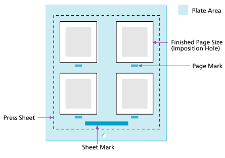
- Sheet marks are placed relative to the plate edge. Depending on the distance you type, you can place the sheet mark on the press sheet or on the plate.
- Page marks are placed relative to the finished page size (the imposition hole).