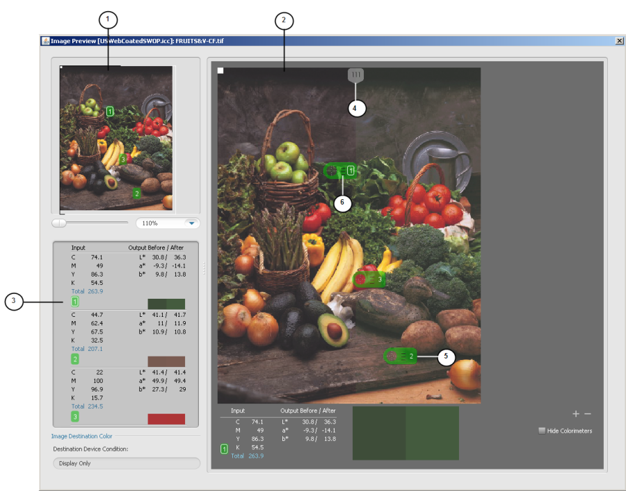
As you adjust color control elements in ColorFlow, you can use the Image Preview window to see the real-time effect of your adjustments on an image file in a split-screen view.
In any of the adjustment dialog boxes in ColorFlow, you can click Preview to browse to an image and see the effect of your adjustments on the image that you select.
You can preview only images that are 8-bit TIFF or JPEG images that in the CMYK color space. You can open both CMYK and RGB image files when you are adjusting device destination profiles.
You can use the Image Preview window to preview images when:
- Adjusting PCO color response
- Adjusting SCO color response
- Adjusting a CMYK color input conversion with a DeviceLink
- Adjusting the device condition profiles
- Adjusting device curves
- Adjusting the PCO profile
Note: The Image Preview window's options vary depending on the circumstances under which you are previewing.
Navigation pane: The image in the navigation pane shows the regions of the image that are affected by the selected adjustment modes. To show ranges for all curve and profile adjustment settings, select the Show Adjustment Range check box. The current magnification of the image is shown in the text box below the navigation pane. A magnification of 100% indicates that the image is displayed using one screen pixel for each pixel in the image file. Similarly, 500% indicates that 5x5=25 screen pixels are used for each pixel in the image file. You can zoom and pan a previewed image in the Navigation pane.
- Image preview pane: Displays the previewed image.
- Colorimeter pane: Displays the tint values of the colors at the Colorimeters' locations.
- Input-output divider: A movable divider in the Image preview pane of the Image Preview window allows you to divide the image into two sections. One section shows the image as it appears prior to your adjustments and one section shows the image as it would appear after your adjustments. Depending on the type of color control element that you are adjusting, values on the left or right side of the Output column will change:
- When you adjust a simulation or conversion curve or DeviceLink, the tint values of inks in the output prior to your adjustments are shown on the left side of the column and remain constant. Tint values of inks in the output, after your adjustments, are shown on the right side of the column and change with your adjustment.
- When you adjust a device curve, the current tint values of inks in the output are shown on the left side and change with your device curve adjustment. Your desired tint values of inks in the output are shown on the right side of the column and remain constant as a reference to the expected output tint after you correct a color shift.
- Colorimeter: A tool used to display the tint values of colors at selected points in the preview image.
- To add a floating colorimeter, click the add button under the image. You can add multiple colorimeters but only one can be selected at a time
- To delete a colorimeter, select the colorimeter and click the delete button under the image
- To temporarily hide all colorimeters from the image, select the Hide Colorimeters check box
- Colorimeter (magnified): Magnifying a colorimeter allows you to see detail without having to magnify the entire image. You can magnify a colorimeter by the following:
- For Windows, select the colorimeter and press the Ctrl key.
- For Mac, select the colorimeter and press the Command key.
