A color setup is the virtual structure that you build to define the color relationship of all of the devices in your printing task, including the conversions that occur between color outputs. A color setup describes relationships, not a workflow—that is, it describes what conversions occur, but not when a conversion occurs in the workflow process.
A color setup manages how its device conditions simulate the Primary Color Output (PCO). PCO is the device condition you choose to be the main color output in a color setup. A PCO can be either the color response of a physical device or an industry specification, such as GRACoL C1. If you want the color output of a printing device to match the color output of a PCO in a color setup, you can add this device as a Secondary Color Output (SCO) in the color setup. ColorFlow aligns an SCO to the color space of the PCO, so that the color produced by the SCO appears similar to the PCO.
If you want to convert data in an input color space to the color space of the PCO, you can add a Color Input (CI). CI is the device condition in a color setup that describes the color space of the input files. Prinergy uses the CI as the source space to reseparate input files to the destination color space of the PCO. If you do not want to reseparate all input files using the color space of the CI, you do not need to include a CI in your color setup.
A complete color setup must include the following:
- One PCO
- A defined simulation target for the PCO, unless the PCO uses a CMYK Reference device condition
- A color response for each device condition
- ICC device profiles (may be required by the Prinergy workflow)
A color setup may also include the following:
- One or more SCOs
- One or more CIs
- Other color control elements, such as curves and DeviceLink profiles
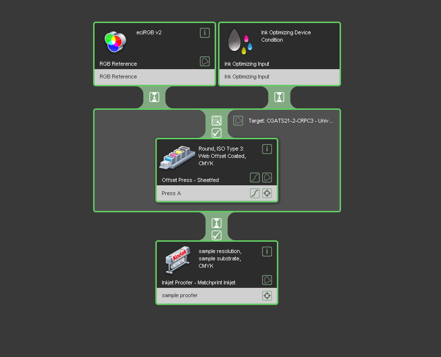
The ColorFlow interface uses the colors green and orange to guide you through the creation of a color setup. When you start a new color setup, the borders and Properties icons of all device conditions in the color setup viewer are orange. After you define the properties of a device condition, other icons in the device condition become orange to indicate that they need to be defined next. When all elements of the color setup have been defined and all color control elements have been calculated, all icons and borders in the color setup are green.
The following image shows an example color setup: