| Sv translation | ||||||||||||
|---|---|---|---|---|---|---|---|---|---|---|---|---|
| ||||||||||||
This topic explains the three options in output process templates that position sheet marks: Locate Sheet Marks Adjacent to list, at Distance box, and Justified list. Important: Use the Virtual Proofing System software to check the sheet mark placement. Alternatively, you can output to a low-resolution TIFF file and view the sheet mark placement in the Copydot Toolkit software.
The Locate Sheet Marks Adjacent to list allows you to place the sheet mark on the left, right, bottom, or top edges of the plate. The sheet mark rotates when positioned on the right and left edges, but not on the top or bottom edges.
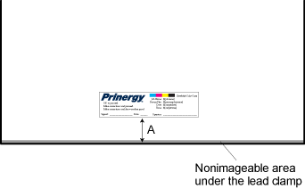
at distance The at Distance box determines how far to position the sheet mark from the edge that you selected in the Locate Sheet Marks Adjacent to list. The distance is shown as A in the following diagram.
Important: When placing the sheet mark on final output, carefully calculate the at Distance value. Otherwise, the sheet mark may print beyond the edge of the press sheet.
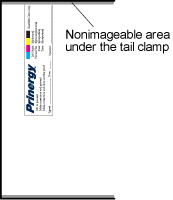
Selecting Right or Left in the Justified list places a sheet mark flush against the edge of the plate, with no border or spacing. In some cases, you may inadvertently place the sheet mark in the nonimageable area under the lead or tail clamp.
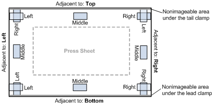
Putting it all together These diagrams (not to scale) show possible combinations of the Locate Sheet Marks Adjacent to and Justified options. Assume that the at Distance value is 6.3 mm (0.25 inches) in all cases. The following diagram shows sheet marks placed on a plate.
|
| Sv translation | ||||||||||||
|---|---|---|---|---|---|---|---|---|---|---|---|---|
| ||||||||||||
Cette rubrique présente les trois options des modèles de processus de sortie pour placer les repères de feuille : la liste Rechercher les repères de feuille adjacents, le champ à distance et la liste Justification. À l'aide de ces trois options, vous pouvez placer les repères de feuille à divers emplacements de la plaque ou de la feuille d'impression. Avant d'effectuer votre sélection, vous devez savoir où doivent apparaître les repères de feuille, connaître la taille de la feuille d'impression et de la plaque et l'emplacement des pinces de tête et de pied. Ceci est particulièrement important lorsque vous placez les repères de feuille sur une plaque. Important : Utilisez le logiciel Virtual Proofing System pour contrôler le placement des repères de feuille. Vous pouvez également sortir un fichier TIFF basse résolution et visualiser l'emplacement des repères de feuille dans le logiciel Copydot Toolkit. Rechercher les repères de feuille adjacents La liste Rechercher les repères de feuille adjacents vous permet de placer les repères de feuille sur les bords gauche, droit, inférieur ou supérieur de la plaque. Le repère de feuille pivote lorsqu'il est placé sur les bords droit et gauche, mais pas sur les bords supérieur ou inférieur.
À distance Le champ à distance indique au système où placer le repère de feuille par rapport au bord sélectionné dans la liste Rechercher les repères de feuille. La distance est indiquée par un A dans le schéma suivant.
Important : Lorsque vous placez le repère de feuille sur la sortie finale, calculez précisément la valeur à distance ; sinon, le repère risque d'être imprimé en deçà du bord de la feuille d'impression. Justification Si vous choisissez Droite ou Gauche dans la liste Justification, le repère de feuille est placé contre le bord de la plaque, sans bordure ni espace. Il arrive que le repère de feuille soit placé, par inadvertance, dans une zone non exposable sous la pince de tête ou de pied.
Rassemblement des éléments Ces schémas (pas à l'échelle) illustrent les combinaisons possibles des options Rechercher les repères de feuille adjacents et Justification. La valeur à distance est définie sur 6,3 mm (0,25 pouces) dans tous les cas. Remarque : dans certaines combinaisons, une partie du repère de feuille est placée dans une zone non exposable sous la pince de tête ou de pied.
|


| Sv translation | ||||||||||||
|---|---|---|---|---|---|---|---|---|---|---|---|---|
| ||||||||||||
该主题解释输出处理模板中用于放置印张标记的三个选项:将页面标记靠近列表、距离框和对齐列表。 使用这三个选项,您可以将印张标记放置在印张或印版上的各种位置。在进行选择之前,必须了解要显示印张标记的位置、印张和印版的大小以及前后定位夹的位置。在印版上放置印张标记时,这尤其重要。 重要: 使用 Virtual Proofing System 软件检查印张标记的布局。或者,也可以输出至低分辨率 TIFF 文件,并在 Copydot Toolkit 软件中查看印张标记布局。 将印张标记靠近 将印张标记靠近列表允许您将印张标记放置在印版的左、右、下或上边。当放置在右边和左边时,印张标记将进行旋转,但如果放置在上边或下边,则不进行旋转。
距离 距离框确定在离将印张标记靠近列表中所选边缘多远的位置上放置印张标记。在下图中该距离显示为 A。
重要: 在最终输出上放置印张标记时,应仔细计算距离值。否则,印张标记可能印刷在印张边缘以外。 对齐 选择对齐列表中的右或左可将印张标记与印版边缘齐平,不留边框或间隔。在某些情况下,您可能会无意中将印张标记放置在前或后定位夹下面的不可成像区域。
放在一起 这些图(不按比例绘图)显示了将印张标记靠近和对齐选项的可能组合。假设在所有情况下距离值均为 6.3 厘米(0.25 英寸)。
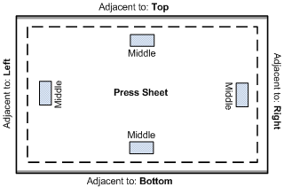
下图显示放置在印张上的印张标记。
|


| Sv translation | ||||||||||||
|---|---|---|---|---|---|---|---|---|---|---|---|---|
| ||||||||||||
In diesem Thema werden die drei Optionen in der Ausgabeprozessvorlage erläutert, mit deren Hilfe Bogenmarken platziert werden: die Liste Bogenmarken platzieren, das Feld im Abstand und die Liste Ausgerichtet. Über diese drei Optionen können Sie Bogenmarken an verschiedenen Positionen auf dem Druckbogen oder der Druckplatte platzieren. Bevor Sie sich für eine Option entscheiden, müssen Sie genau wissen, wo die Bogenmarken angezeigt werden sollen, sowie die Größe des Druckbogens und der Druckplatte und die Position der oberen und unteren Klammern kennen. Dies ist besonders wichtig, wenn Sie die Bogenmarken auf der Druckplatte platzieren. Wichtig: Verwenden Sie die Virtual Proofing System-Software, um die Platzierung der Bogenmarken zu überprüfen. Alternativ können Sie in eine niedrig auflösende TIFF-Datei ausgeben und die Platzierung der Bogenmarken in der Copydot Toolkit-Software anzeigen. Bogenmarken platzieren Über die Liste Bogenmarken platzieren können Sie eine Bogenmarke an der linken, rechten, unteren oder oberen Kante der Platte platzieren. Die Bogenmarke wird gedreht, wenn Sie sie an der rechten oder linken Kante platzieren, jedoch nicht beim Platzieren an der oberen oder unteren Kante.
Im Abstand Im Feld im Abstand geben Sie an, wie weit entfernt eine Bogenmarke von der in der Liste Bogenmarken platzieren gewählten Kante platziert werden soll. Dieser Abstand ist im folgenden Diagramm als "A" angegeben.
Wichtig: Beim Platzieren einer Bogenmarke auf der Endausgabe muss der Wert im Feld im Abstand sorgfältig berechnet werden. Andernfalls wird die Bogenmarke möglicherweise über die Kante des Druckbogens hinaus gedruckt. Ausgerichtet Wenn Sie in der Liste Ausgerichtet die Option Links oder Rechts auswählen, wird die Bogenmarke bündig mit der entsprechenden Kante der Druckplatte platziert (ohne Rand oder Abstand). In einigen Fällen platzieren Sie die Bogenmarke eventuell unabsichtlich im nicht bedruckbaren Bereich unter den oberen und unteren Klammern.
Kombinieren der Bogenmarkenoptionen Die folgenden Diagramme (nicht maßstabsgerecht) zeigen mögliche Kombinationen der Optionen Bogenmarken platzieren und Ausgerichtet. Dabei wurde in allen Beispielen für die Option im Abstand der Wert 6,3 mm (0,25 Zoll) angenommen. Das folgende Diagramm zeigt die auf einer Druckplatte platzierten Bogenmarken. Anmerkung: Bei einigen Kombinationen befindet sich ein Teil der Bogenmarke im nicht bedruckbaren Bereich unter den oberen und unteren Klammern.
Das folgende Diagramm zeigt die auf einem Druckbogen platzierten Bogenmarken.
|


| Sv translation | ||||||||||||
|---|---|---|---|---|---|---|---|---|---|---|---|---|
| ||||||||||||
このトピックでは、シート マークを配置するための出力プロセス テンプレートの 3 つのオプションについて説明します。シート マークを配置する位置リスト、距離ボックス、および配置リストです。 これら 3 つのオプションを使用して、シートや版のさまざまな位置にシート マークを配置できます。選択を行う前に、シート マークを表示させたい場所、シートと版のサイズ、およびくわえ(リーディング エッジ クランプ)とくわえ尻(トレーリング エッジ クランプ)の位置を確認してください。これは、シート マークを版上に配置する際に特に重要です。 重要: Virtual Proofing System ソフトウェアを使用してシート マークの配置を確認してください。または、低解像度の TIFF に出力し、シート マークの配置を Copydot Toolkit ソフトウェアで表示することもできます。 シート マークを配置する位置 シート マークを配置する位置リストでは、シート マークを版の左、右、下、または上の端に配置できます。シート マークは、左右の端に配置された場合回転しますが、上下の端に配置された場合は回転しません。
距離 距離ボックスでは、シート マークを配置する位置リストで選択した端から、シート マークをどれだけ離して配置するかを指定します。この距離は下の図の A です。
重要: 最終出力にシート マークを配置する場合、距離ボックスの値は慎重に計算してください。計算が誤っていると、シート マークがシートの端の外に印刷される場合があります。 配置 配置リストで右または左を選択すると、シートマークが版の端にぴったり寄せられ、境界やスペースなしで配置されます。場合によっては、シート マークが、くわえ(リーディング エッジ クランプ)またはくわえ尻(トレーリング エッジ クランプ)の下の印刷できない領域に誤って配置されることがあります。
すべてを組み合わせる 以下の図(縮尺は合っていません)では、シート マークを配置する位置と配置オプションの可能な組み合わせを示しています。いずれのケースでも、距離の値は 6.3 mm(0.25 インチ)であると想定しています。
|


| Sv translation | ||||||||||||
|---|---|---|---|---|---|---|---|---|---|---|---|---|
| ||||||||||||
Este tema explica las tres opciones de las plantillas de proceso de salida que colocan las marcas de hoja: La lista Localizar marcas de hoja adyacentes, el cuadro a distancia y la lista Justificada. Con estas tres opciones, puede colocar una marca de hoja en distintas posiciones de la hoja de impresión o de la plancha. Antes de elegir una u otra opción, es preciso saber dónde quiere que aparezca la marca de hoja, el tamaño de la hoja de impresión y de la plancha y la ubicación de los dispositivos de sujeción de entrada y salida. Esto es particularmente importante al colocar la marca de hoja en una plancha. Importante: Utilice la aplicación Virtual Proofing System para comprobar la colocación de la marca de hoja. De otro modo, puede generar la salida en un archivo TIFF de baja resolución y ver la ubicación de la marca de hoja en la aplicación Copydot Toolkit. Localizar marcas de hoja adyacentes a La lista Localizar marcas de hoja adyacentes a permite colocar la marca de hoja en los bordes izquierdo, derecho, inferior o superior de la plancha. La marca de hoja rota cuando se coloca en los bordes derecho o izquierdo y mantiene su orientación cuando se coloca en los bordes superior o inferior.
a distancia El cuadro a distancia determina a qué distancia del borde seleccionado en la lista Localizar marcas de hoja adyacentes a. La distancia está identificada con la A en el diagrama que figura a continuación.
Importante: Al colocar la marca de hoja en la salida final, debe prestar especial atención al cálculo del valor del cuadro a distancia. De otro modo, cabe la posibilidad de que la marca de hoja se imprima fuera del borde de la hoja de impresión. Justificada Al seleccionar Derecha o Izquierda en la lista Justificada, la marca de hoja se coloca alineada con el borde de la plancha, sin dejar ningún borde espacio. En algunos casos, es posible que coloque la marca de hoja de forma inadvertida en el área de no exposición que se encuentra bajo los dispositivos de sujeción de entrada o salida.
Cuadro resumen Estos diagramas (fuera de escala) muestran las posibles combinaciones de las opciones Localizar marcas de hoja adyacentes a y Justificada. Se asume que el valor de a distancia es 6,3 mm (0,25 pulgadas) en todos los casos. Nota: en algunas combinaciones, parte de la marca de hoja está colocada en el área de no exposición que se encuentra bajo los dispositivos de sujeción de entrada o salida.
|
| Sv translation | ||||||||||||
|---|---|---|---|---|---|---|---|---|---|---|---|---|
| ||||||||||||
This topic explains the three options in output process templates that position sheet marks: Locate Sheet Marks Adjacent to list, at Distance box, and Justified list. Important: Use the Virtual Proofing System software to check the sheet mark placement. Alternatively, you can output to a low-resolution TIFF file and view the sheet mark placement in the Copydot Toolkit software.
The Locate Sheet Marks Adjacent to list allows you to place the sheet mark on the left, right, bottom, or top edges of the plate. The sheet mark rotates when positioned on the right and left edges, but not on the top or bottom edges.
at distance The at Distance box determines how far to position the sheet mark from the edge that you selected in the Locate Sheet Marks Adjacent to list. The distance is shown as A in the following diagram.
Important: When placing the sheet mark on final output, carefully calculate the at Distance value. Otherwise, the sheet mark may print beyond the edge of the press sheet.
Selecting Right or Left in the Justified list places a sheet mark flush against the edge of the plate, with no border or spacing. In some cases, you may inadvertently place the sheet mark in the nonimageable area under the lead or tail clamp.
Putting it all together These diagrams (not to scale) show possible combinations of the Locate Sheet Marks Adjacent to and Justified options. Assume that the at Distance value is 6.3 mm (0.25 inches) in all cases. The following diagram shows sheet marks placed on a plate.
|